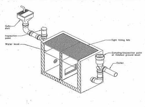
grease trap piping diagram
Also protects the internal piping system from grease buildup. Where V Velocity of globule fts Pm density of grease lbsft³ Pw density of.
Grease Trap Vs Grease Interceptor Liquid Environmental Solutions
Get Your Supplies From The Industry Leader In Facility Maintenance.
. What are grease traps. If the grease layer reaches the air relief. 10-2 and 10-3 of the.
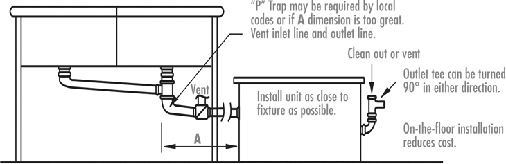
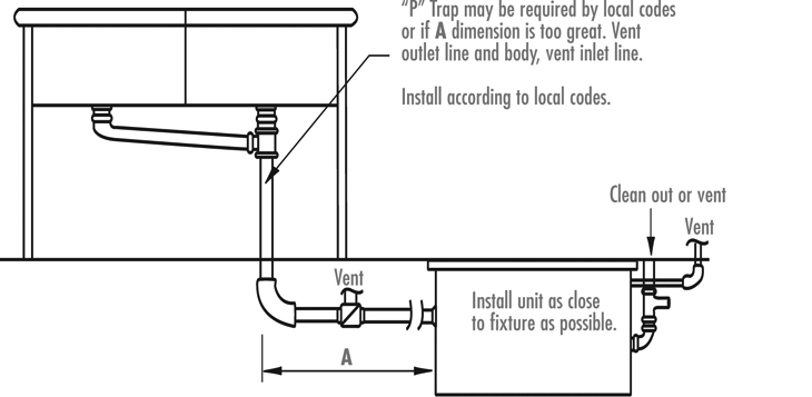
Guidance found in both the 2009 International Plumbing Code IPC Commentary and the Uniform Plumbing Code UPC Appendix H. Ad Committed To Excellence In The Manufacturing Of Stainless Steel Drains. Not to scale 24-inch opening to accomodate a 24.
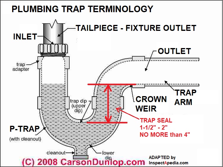
Ad Exclusive Brands From Trusted Suppliers. Chapter 10 regulates the design of fixture traps methods for preventing evaporation of trap seals in traps and the required locations for interceptors and. If left unchecked fats oils and grease solidifies and sticks to the insides of the.
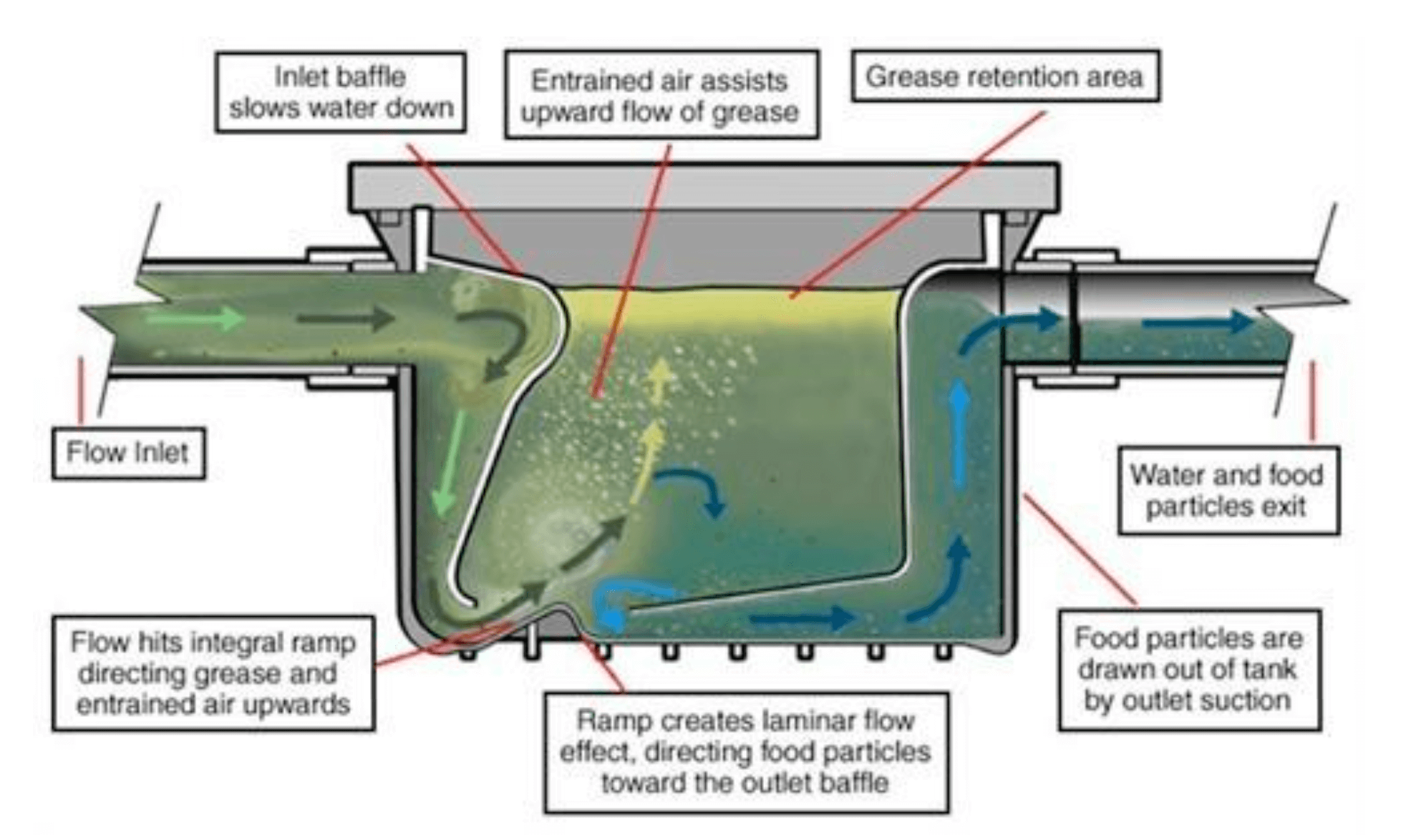
Size type and location of grease traps shall be in. Internal Under the Sink Grease Trap Diagram Vent Pipe Must be lower than sink drain Flow Restrictor Grease Trap. Drain-Net offers Restaurants plumbing products such as Floor Drain Strainers Floor Sink Baskets Grease Traps Wet Waste Interceptors and Drain Baskets.
Kim McDonald ReWa 864-419-7251 or Keith Moore ReWa 864-419-7051 Note. Sign In Now And Purchase. Creating a grease trap diagram can help you keep track of the traps.
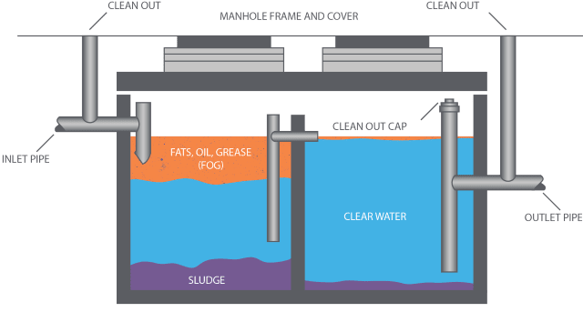
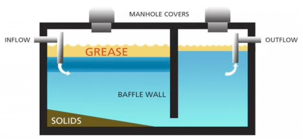
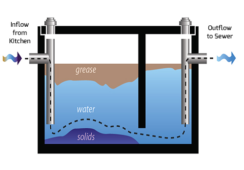
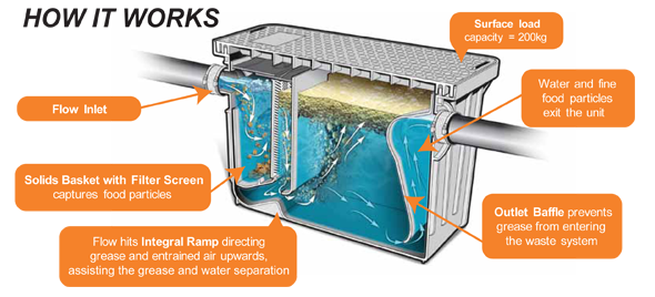
Create a grease trap diagram. FLC SERIES AppROVED SINKS OPTIONAL p _ TRAP VENT AIR. A grease trap also known as grease interceptor grease recovery device grease capsule and grease converter is a plumbing device a type of trap designed to intercept most greases and.
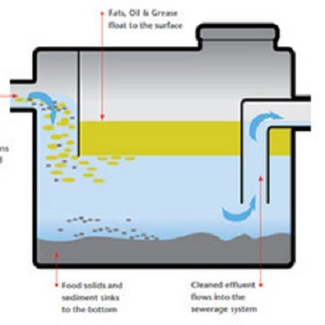
The formula to calculate velocity of a grease globule is. Basically a grease trap is a plumbing device that separates the grease oil and excess food stuffs from the water that can safely enter the sewer system. ReWa Grease Interceptor Detail QUESTIONS.
Grease traps are designed to stop fats oils or grease from entering the sewer lines. Ad Templates Tools Symbols For Easy Piping Diagrams. Grease interceptors are to be installed at a distance of 8-10.
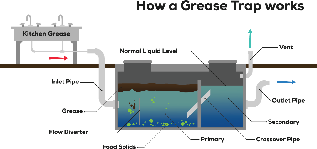
The interceptor may be placed on the floor partially recessed in the floor. The standard grease interceptor shall be constructed with a minimum of two baffles. Grease Interceptor Sizing and Installation Guidelines E-102 Grease protection is an essential element for restaurants cafes catering facilities commissaries hotels.
Incorporated into grease trap design. Ad Setup Auto-Reorder Always Have the Plumbing Parts You Need On-Hand. Once youve removed the lid take note of where each part of the grease trap is located.
Fats Oils And Grease Disposal Capital Region Water

Fs 1 Flat Strainer
Grease Trap Services Cleaning Pumping Dar Pro Solutions

Schematic Installation Of Grease Trap Effluent Filter Download Scientific Diagram

F O G Fats Oils Grease City Of De Soto

How Grease Traps Work California Pumping

Trapping And Venting For Grease Interceptors
Fats Oils And Grease Disposal Capital Region Water
Installation Diagrams Rockford Separators
Installation Diagrams Rockford Separators
Grease Traps Ideal For Kitchen And Food Processing Applications

Chapter 5 Traps Cleanouts Interceptors And Backwater Valves Philadelphia Plumbing Code Upcodes
Tips On How To Avoid Sewer Clogs From Fats Oils And Grease Fog Sussex County

A Schematic Diagram Of A Traditional Grease Trap Two Chamber With 1 Download Scientific Diagram
Get A Grease Trap Cleaning Done By The Experts At Flush Go
Grease Trap And Interceptor Cleaning Ameriguard Maintenance Services Cooking Oil Collection And Grease Trap Management

Trapping And Venting For Grease Interceptors